Cold Gas Thruster Nozzles
To rapidly test multiple iterations of nozzles and different methods of manufacturing in a low temperature environment, I 3D printed some nozzles designed to be attached to an air compressor. This allowed me to test 3D printed parts’ precision and their pressure capabilities in a non-sealed application.
Design Objectives
These nozzles were designed to provide thrust given an input of air at 90 psi and 4.0 SCFM. A converging only, perfectly expanded, and over expanded version were created, and the resultant thrust was measured as an output rather than an objective. The biggest goal here was to see if I could achieve supersonic exit velocities with a 3D printed part.
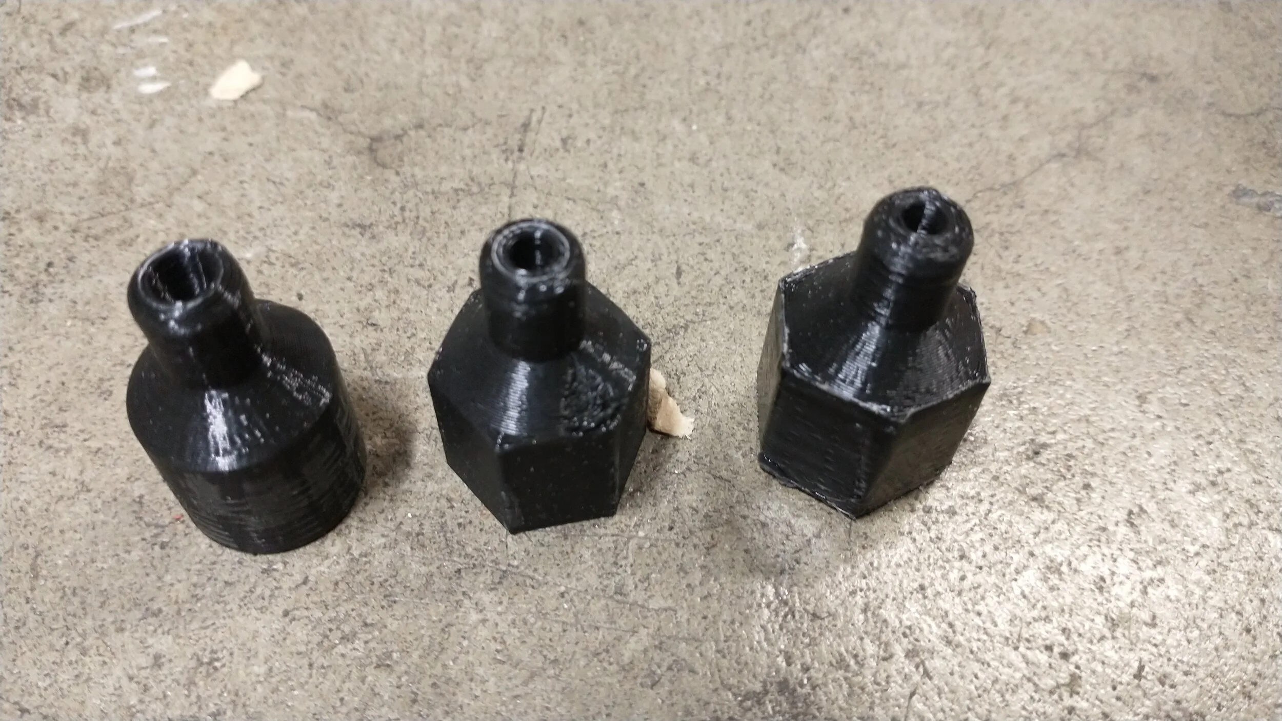
Converging Only
Converging-Diverging, Perfect Expansion
Converging-Diverging, Over Expanded
Calculations

The above equation is what I used to calculate the throat area of the nozzles at the conditions provided by the compressor. In this case, since the fluid is air at relatively room temperature, the heat capacity ratio is γ=1.4. Given the molar mass of air, the specific gas constant R=287.05 J/kg*K. The mass flow rate we can calculate from the advertised volumetric flow rate of the compressor. If ṁ=ρQ, and ρ=P/RT, the mass flow rate comes out to ṁ=0.0136 kg/s. Pt and Tt are pressure and temperature at the throat. There are a couple easy ways to get these, one is an isentropic flow table (from the back of a textbook) and the other is NASA’s CEA, a program used for calculating various variables involved in a rocket engine. Both have their assumptions, but they will provide a good enough approximation. Using the input conditions for flow velocity and pressure, the throat pressure comes out to about Pt=250 K, and the throat temperature comes out to about Tt=250 K. All this considered, the throat area comes out to 9.265 mm^2, and with a factor of safety of 1.25 for printer inaccuracy, At=7.412 mm^2.
The nozzle exits were determined in the same way the throat temperature and pressure were. Using CEA or an isentropic flow table, the exit area to throat area ratio for a perfectly expanded nozzle comes out to Ae/At=1.6, or Ae=11.85 mm^2.
Testing
The test setup is pictured below. A kitchen scale was used for thrust measurement, and a pressure regulator and a ball valve were used to control flow. None of the nozzles seemed to have significant differences in thrust for the initial 3D printed configurations, as they all resulted in about 4.5 N (1 lbf) of thrust, which is significantly lower than the calculated thrust for the converging only nozzle, given by the equation:
Ft=ṁV+PA
Where ṁ is mass flow rate, V is exit velocity, P is nozzle pressure, and A is nozzle area. This comes out to ~6.8 N (~1.5 lbf).
Results
Unfortunately, a significant difference in thrust was not found between converging only and a converging-diverging nozzle. This leads me to believe that either the inaccuracy of the throat diameter or the leaks between the layer lines caused the exit flow to not be supersonic.
Lessons Learned
Given the accuracy of the Ender 3 on a small scale such as this, a subtractive manufacturing technique would be preferred. The plan is currently to buy a brass NPT plug and machine out a more precise throat diameter and see if the resulting thrust is more in line with my converging only calculations.