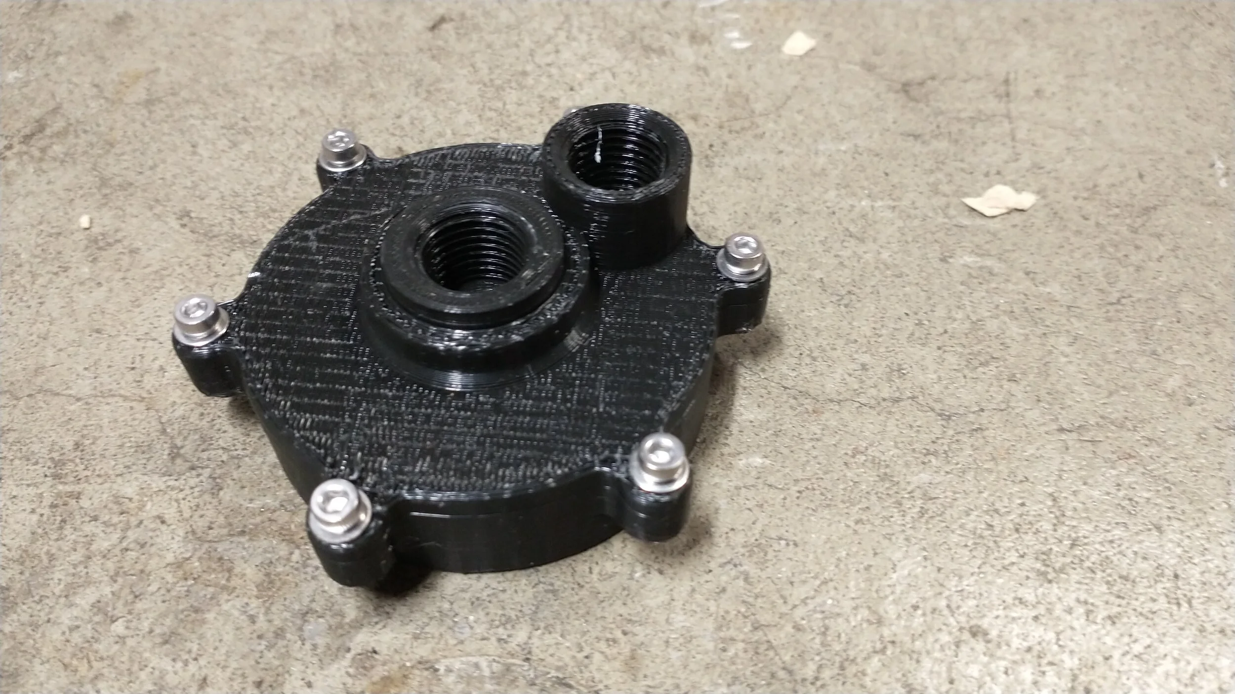
Injector/Combustion Chamber
Design Objectives
The initial design of the injector was done without many engine constraints in mind. The goal was to test fluid-gas impingement eventually for a isopropyl-air rocket engine, but in a quick, easy to manufacture environment. A rough combustion chamber diameter was assumed, and all other parameters were derived based on available hardware. A more in depth design process will be done with values provided by the Liquid Rocket Engine Nozzle section when an adequate general impingement solution is found.
Approach
The design consists of a single, central hole modeled after a standard full cone spray nozzle used typically for agricultural purposes. This central hole was designed to be the liquid interface, as it has less opportunities for leakage than the outer path. The air was then pumped into an arbitrary number of holes surrounding this hole, angled inward toward the middle cone. In theory this would mix the air with the fuel flow, which would already have a small droplet size, creating a good mixture of reactants for combustion. However, in practice, the central liquid flow turned out to be mostly a jet, and the air jets had little effect on it. See below for testing photos and footage of the initial design.
A test of both flowpaths, liquid water in the middle and compressed air in the outer path. Ideally you would see atomization and a fine mist of droplets, but the inner spray nozzle didn’t work, resulting in a narrow jet mostly unaffected by the air jets.
A full duration test of the inner flow path. At the end you can see decent atomization, but only because the water was low and air and water were mixing in the inner flow path before coming out of the injector.
A time controlled test of hte inner flow path with water only. Ideally you would also see a cone spray here but the result is a narrow jet.
Results
As you can see from the above videos, the injector design failed to atomize the liquid coming out of the center flow path. A design utilizing multiple central flow paths and direct impingement of the flow (as opposed to relying on the spray nozzle to eject the liquid in a cone) will be preferred, as a large pressure delta is required for a spray nozzle to achieve a good flow rate with atomized droplets.
The 3D printed parts also leaked in various points, including directly through the face of the lid. This means that a different manufacturing technique would need to be used, even for testing that would be good enough to verify a design.
Lessons Learned
While I already knew this would be the case, 3D printed parts leak uncontrollably, even at 100% infill. This makes them unsuitable even for design testing except at the most rudimentary levels. O-rings are also only marginally effective with these parts, as the plastic often does not have the rigidity to compress the O-ring to the desired level.
Even a very simple injector design will require some custom machining. With my limited manufacturing capabilities, this makes it hard to move forward without external help. The next step of this design will be to explore other options for injector design (a simpler impingement design, a pintle, or even a coaxial swirl design) that would perhaps be easier to manufacture. These will also be integrated with the requirements from the nozzle section, so that they will be more representative of what will be in the actual engine.