
One of the first options I explored for this engine was compressing air with a custom centrifugal compressor to achieve the necessary flow rate to make an air breathing engine. This was overly optimistic for a few reasons, and I have since tabled this approach to be continued at a later time. Below you can find the design process and calculations that resulted in that decision, as well as considerations moving forward.
Summary
I began this project with the hopes of creating a compressor that would supply compressed air at roughly 125 psig at a flow rate large enough to supply a small liquid rocket engine. I quickly realized a few major issues with my approach, namely the power consumption and temperature requirements of such a system. In my first attempt at producing compressed air, I ended up only creating a blower fan, as I was unaware of the fundamental principles of a centrifugal compressor. Many compressors rely on a piston based system that compresses a certain volume of air and releases it into a tank before letting in another batch, but this has its drawbacks, mainly in terms of mass flow and size. To get a significant mass flow, a larger cylinder or faster rpm system must be used, and even then the flow is not consistent due to the inlet and outlet strokes of the piston. A centrifugal compressor has an advantage in that it can output a high mass flow rate in a relatively small amount of space compared to other designs. However, its main method of compression is different than that of a piston based volume compression system. A centrifugal compressor works mainly by imparting kinetic energy into the fluid, and then using a diffuser to convert that kinetic energy into a static pressure rise. The critical component that differentiates a blower fan from a compressor is this diffuser, which is noticeably missing from my earlier designs. In the following sections, I will go further into detail on the calculations and design decisions made for this project.
Impeller Design
Initial Concepts
My first pass at an impeller consisted of a forward-swept design intended for use at subsonic tip speeds. I started with the assumption that a 3D printed impeller might be able to be somewhat effective, but I quickly realized this was incorrect. Because centrifugal compressor effectiveness greatly increases with tip speeds above Mach 1, the resultant blade stress would likely be too much for a PLA even at room temperature, which is made worse by the fact that PLA has a glass transition temperature of around 60°C. This means that at any reasonable compression ratio, the temperature of the air at the impeller exit and diffuser would be high enough to rapidly reduce the integrity of the part.
I decided to go along with the design in the hopes that another material could be used, such as aluminum, which is relatively cheap and easy to cast into the complex shapes needed for an impeller.
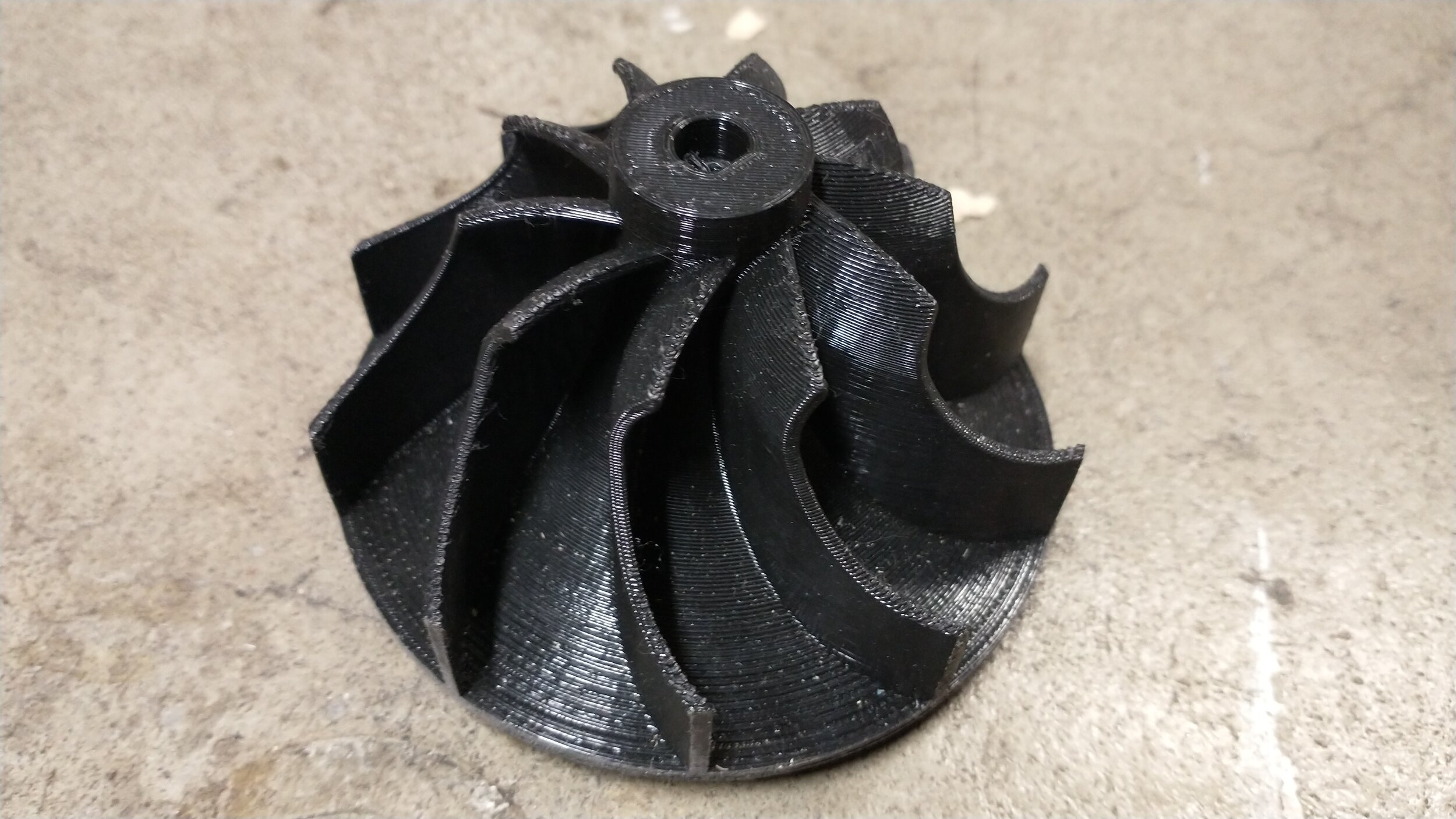
Images of the first attempt (essentially a 100 W blower fan) can be seen below.

A frontal view of the inlet

A rear view of the housing, including the motor mount

Two versions of the impeller, one with inducer vanes and one without.
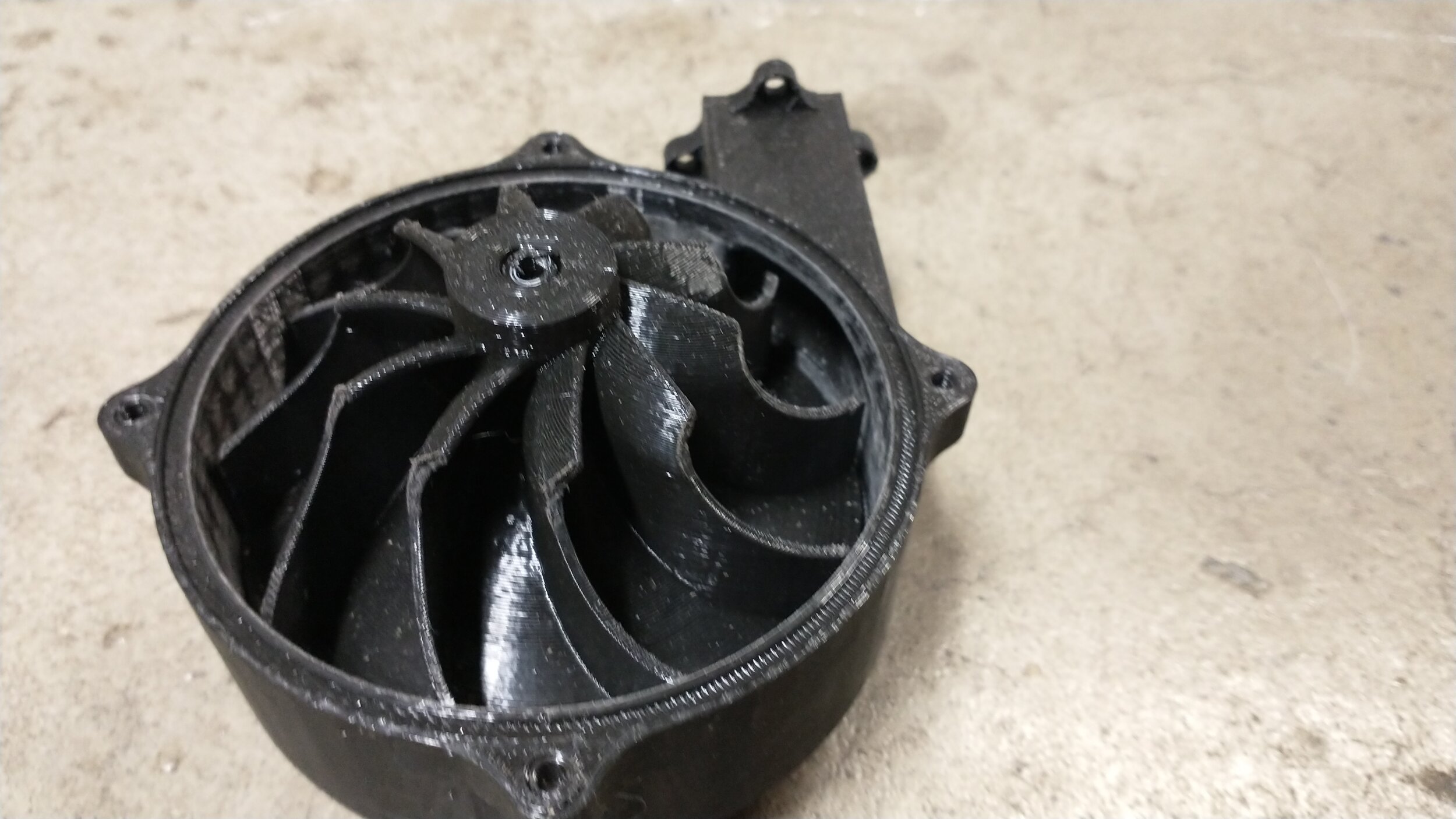
A view of the impeller and housing with the lid removed (outlet is visible)

The impeller, including inducer vanes
Design Calculations
There are two big constraining factors of this project, one being rotational speed (increasing blade stress and added complexity) and the other being temperature rise across the compressor. The temperature difference across the impeller can be determined with a simple shaft power equation, namely:
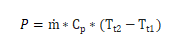
Where P is shaft power ṁ is mass flow rate, Cp is the specific heat capacity of air, and Tt1 and Tt2 are the temperatures at the inlet and outlet of the impeller, respectively. I used a Cp of 1004 J/kg*K, and since I had a 100 W DC motor, I used that for P. At even a low flow rate (0.05 kg/s), the temperature delta across the impeller would be only about 2°C. To turn this into a compression ratio, I used the equation:
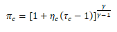
Where πc is the compression ratio, ηc is the adiabatic efficiency, usually ~0.7 for similar compressors (so I used 0.6 given the nature of the project), τc is the temperature ratio (τc=Tt2/Tt1), and γ is the heat capacity ratio for air (γ=1.4). Using the 2°C difference from the last section, this only gives us a compression ratio of about 1.01, or a pressure rise of 0.2 psi from atmospheric pressure. To achieve the desired pressure rise of 125 psig at this flow rate, a power of 21.1 kW (28.3 hp) would be required, and the outlet temperature of the air would be around 700 K. This rules out using 3D printed parts, and makes this form of compression impractical for this project.
Results
Given the almost negligible compression ratio of the current version of the compressor, I have moved on to other methods. I had originally thought this would be a more interesting way to compress the air necessary for this engine, but it proved to be much more demanding than is worth it for this project. To get the required compression ratio, a much larger motor and a much higher temperature compatible material must be used. For the time being, I have shelved this project to be continued at a later date, and perhaps at a much smaller scale.