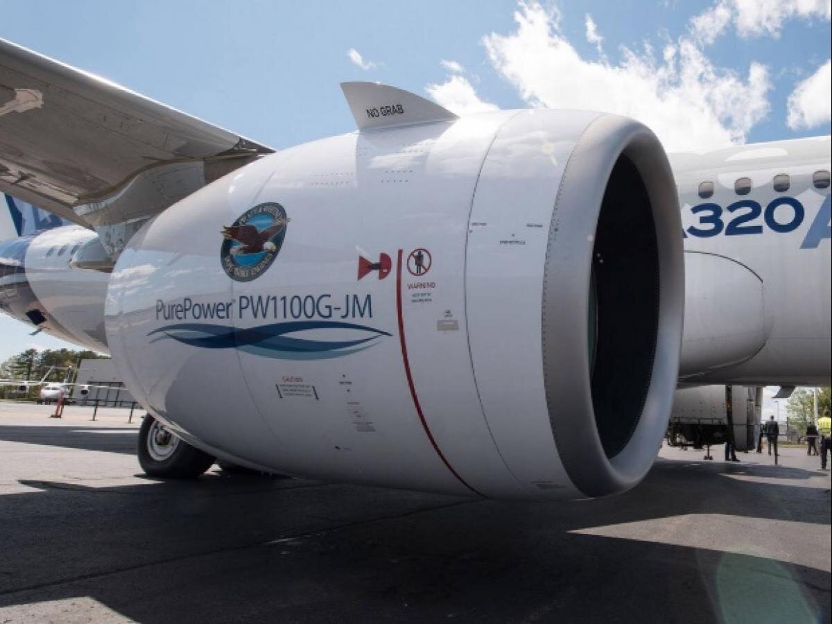
Pratt & Whitney PW1100G Sealing Component Design
Sealing Component Design Background:
Looking to improve on lifetime of certain components
Maintaining a certain amount of cooling airflow throughout the length of the engine is critical, especially throughout the later stages of the turbine
By improving and fixing issues with existing sealing interfaces, you can significantly affect the lifetime of parts downstream of the seal
Skills Utilized:
Fatigue/creep analysis - I calculated the fatigue and creep life of the sealing components using a damage method over a flight profile to make sure the seal would withstand the life requirements
FEA - I performed 2D FEA in ANSYS Mechanical APDL to generate stress inputs into the fatigue analysis
Technical drawings - I generated drawings for the seal components based on similar sealing solutions
Design Objective:
Design a seal with a lifetime that is non-limiting relative to other components
Lifetime is defined as the time it takes for the seal to deform enough to bring the pressure differential to an undesirable value
Constraints:
The seal must fit within an already existing seal cavity without major modifications to surrounding parts
The part must withstand the thermal demands of the high-pressure turbine for a specified amount of flights
The part must be relatively cheap and manufacturable, as the design was intended to be put into a test engine for verification in the near future

Approach:
Conceptually design a 2D cross section that looks like it will roughly handle the changing cavity size due to thermal expansion without losing too much pressure
Determine maximum dimensions of seal that allow for the part to do its job without interfering/pinching itself on surrounding components
The part must fit within the tolerance stackup of the surrounding components at assembly temperature and not interfere as the parts heat and cool during a flight
Determine creep and Low Cycle Fatigue life of part using flight and material data gathered from testing
Pratt & Whitney uses proprietary materials for many components, and data on these materials (such as S-N curves, thermal expansion coefficients, etc.)
Temperatures and pressures at different points in the engine over the course of a flight have also been recorded, and this data, in combination with the material data, can be used to calculate the creep/fatigue life of the part
Collaborate with the surrounding components’ engineers to make adjustments and ensure my solution was valid
Create drawing specifications for final geometry
Results:
The parts I designed were intended to be put in the upcoming test engine
Theoretically the parts achieved the design objective of outlasting the surrounding components while minimally affecting the surrounding components
Lessons Learned:
Data driven analysis is invaluable
High temperature engineering is a completely different process than something like consumer goods
Importance of quick collaboration