AerospaceNU Airframe Development Lead
Background:
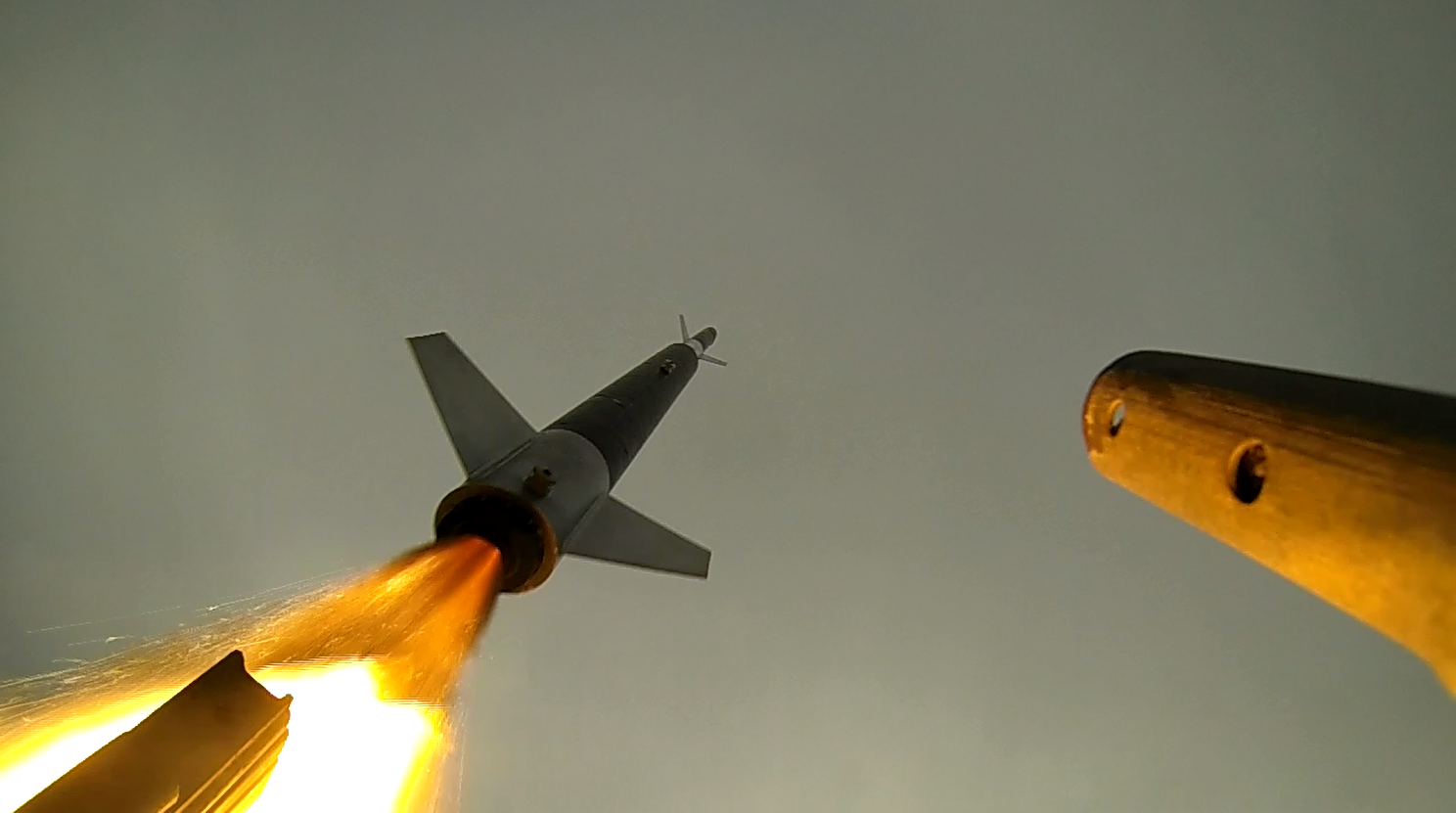
In my time in the AerospaceNU club at Northeastern, I worked on Project Karman, an ambitious project centered around putting a student designed and built rocket beyond the Karman Line, at an elevation of 100km. My job was to lead the team that designed and constructed the rocket pictured below. This rocket’s purpose was to be the upper stage of a subscale test flight that would test flight capabilities and subsystems that would eventually go on the final rocket.
Skills Utilized:
CAD - I was in charge of managing the assemblies and designing some of the parts
Team management - led roughly 10 people towards creating the airframe, which included fin can, fueselage, parachute deploy mechanism, and camera bay construction
Rocketry basics - The rocket was designed from scratch in OpenRocket, which included weight placement, fin design, motor selection, and relative CG and CP placement
Skill instruction - I instructed the newer team members on rocketry basics and Solidworks part design, as well as assembly collaboration basics
Design Objectives:
Design and build an airframe capable of supporting the necessary subsystems to test for a full scale launch
Camera housing section
Modular Fin section
Custom parachute deploy system
Constraints:
Rocket should utilize an off-the-shelf motor with a similar diameter and length so the design is future compatible for more tests
Airframe diameter should be 6”
Approach:
First a general design was created in OpenRocket (see below for screenshot). This allowed me to determine if all the components would give the necessary thrust to weight ratios and if the center of pressure and center of gravity would balance out.

•Designed transparent section to house two 360° cameras as well as a battery and GPS
•Rocket was designed with a custom parachute release system that would allow for more consistent deployment of the main parachute at a certain altitude while maintaining the compact nature of having both drogue and main parachutes in the same cavity
•A modular fin system allowed for both sturdier construction of fins at higher velocities and temperatures as well as easier replacement of fin geometries depending on the motor being used

Transparent Section Design:
Transparent section housed two 360° cameras and a GPS due to the carbon fiber body not being suitable for live data transmission from the GPS
Connects the nosecone with a screw on attachment to allow for maintenance of the pitot tube assembly housed within
Aft aluminum bulkhead acts as a parachute attachment point, as the rocket separates there
Threaded rods take thrust and drag loads to prevent acrylic housing from cracking
Results:
The rocket launched on schedule, but unfortunately the recovery systems failed and the rocket was not recovered. The rockets trajectory and apogee seemed to be nominal, but the rocket never separated, and came down on a ballistic trajectory. The cause of the failure is unknown, as the rocket was never fully recovered, but it is suspected that an electronics failure was the cause, as the mechanical system governing separation was tested just prior to use. See below for the aftermath.

A view of the thrust plate and fins on the rear of the rocket after lawn darting itself into the ground from about 8000 ft.
Lessons Learned:
There were a few major lessons from this project, one of which was how to manage and utilize the strengths of the people on the team effectively. Learning how to get things done and utilizing the experience and knowledge of the older members of the team while still balancing the education and training of newer members proved to be quite a challenge. However, the project launched on time and the airframe seemed to work, and I think the newer members learned a lot about rocket basics and the subsystems required for these types of rockets.
I also learned a couple design oriented things, specifically about beam buckling. The threaded rods on the transparent section buckled on the previous rocket when one of the fins came off mid flight and the vehicle experienced an RUD. Unfortunately, both cameras were destroyed and no footage was recovered. On this rocket, we went with 3/8” threaded rods instead of 1/4” to increase the buckling strength. This would hopefully protect the cameras in the event of a failure in flight.