Brewbird Coffee Bean Dosing Fixture
Summary:
Brewbird is a small coffee machine startup based out of San Mateo, CA. I worked for them as a design engineering contractor to bring to life a fixture that would rapidly fill several individual pods at a time with coffee beans in order to meet growing demand as more machines were rolled out. Below are images of two different versions I designed and built.
Skills Utilized:
CAD using Solidworks - designed system from scratch, including the sheet metal and machined parts. Utilized as much off-the-shelf equipment as possible without sacrificing functionality.
Prototyping - 3D printed several plate design options to test for which would best prevent the beans from jamming before spending money on a machined part.
Assembly/troubleshooting - Assembled the system and used it to make enough pods to meet initial demand. Created second version using this information that improved cycle time and usability while reducing the cost and number of parts significantly.
Vendor sourcing/communication - selected machining and sheet metal vendors and worked with them to reduce price and increase manufacturability.

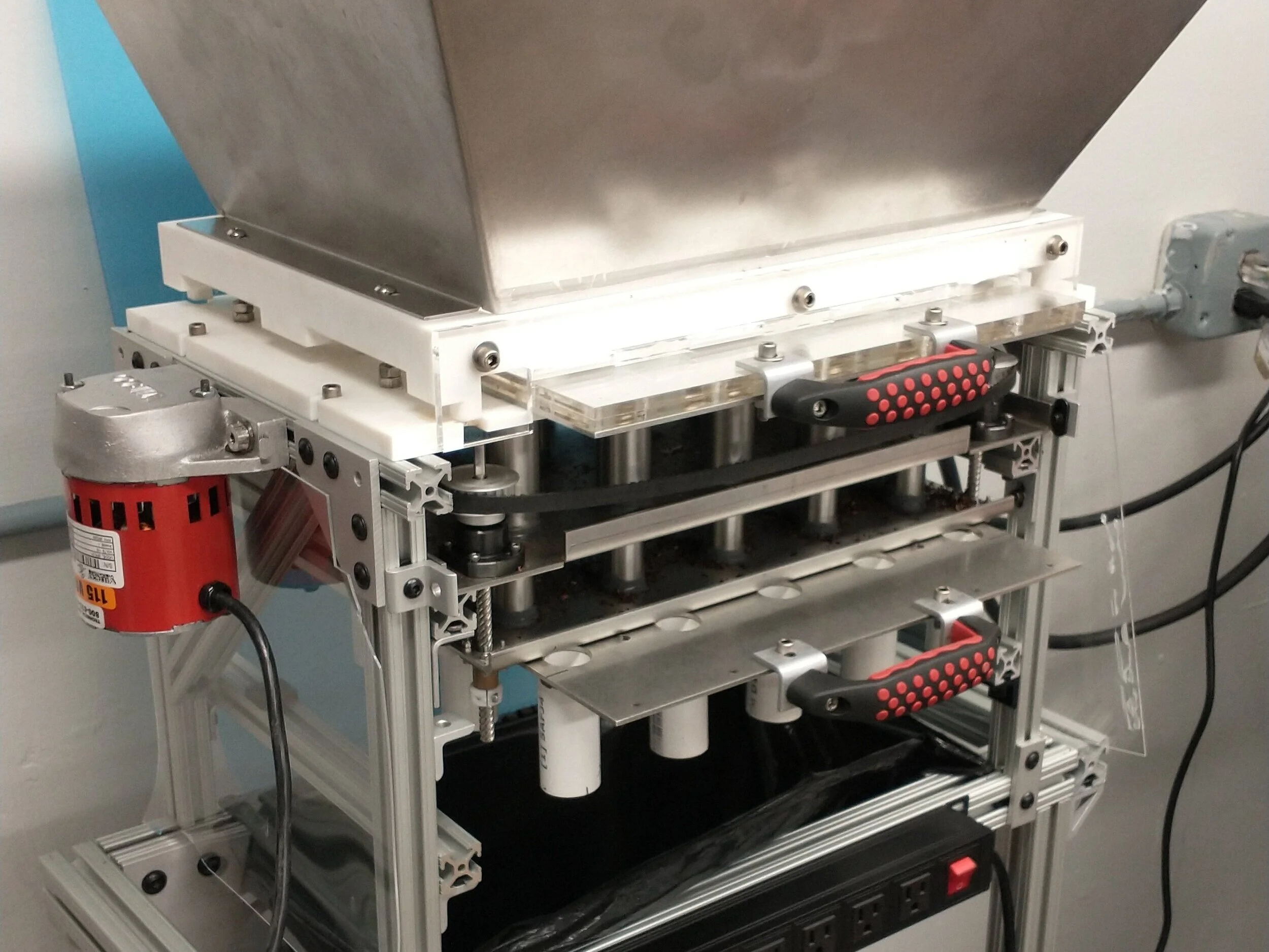
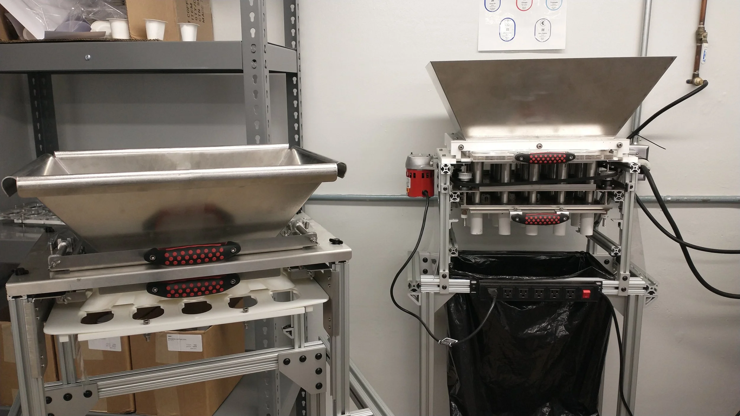
A view of the prototype machine as it stands in the warehouse. The hopper adapter is the white piece the hopper sits on, and the top sliding plate is attached to the top red handle (both of these are pictured below as CAD screenshots). The trash bag and bin are there to catch any extra beans that fall during the process. They also help with emptying the machine when a run of beans is completed.

The second version of the machine, including drastically less parts, pneumatic cylinders for automatically sliding the plates in and out, as well as some ergonomic improvements, such as rounded edges and reduced height.
Problem/Background:
Brewbird makes a coffee machine that uses a pod based system for brewing, somewhat analogous to a Keurig system. These pods are filled with a specific volume of whole beans, which changes with the type of bean or roast being used. In order to fill these pods, the previous method was using a measuring cup and pouring the beans into pods directly by hand. While this product is only in the beta phase, even initial pod quantities would be hard to fill with this method, so a quick, reliable, and accurate method was needed. That’s where this machine comes in.
Design Objectives:
Accurate, adjustable delivery of specific mass of beans to a pod (within 1 gram)
5 second cycle time to fill a full tray (15 pods)
Assembly and disassembly of the machine for cleaning should take 5 minutes or less each
Constraints:
The main constraints for this project are:
The machine must be made of food safe materials (PBT, Stainless Steel, etc.)
The machine must have a maximum hopper height of less than 6’ to accommodate ergonomic movement
The machine’s removable pod tray must be:
Less than 1 lb without coffee beans
34-36” off the ground for ergonomic reasons
The machine (not including the stand) should be 30 lbs or less
The hopper should hold at least 20 lbs of coffee beans
Approach:
The design of the machine is centered around two telescoping tubes with shutoff plates at either end (the plates with handles). When the handles are pulled out, they close off the tubes, and when they are pushed in, they allow beans to flow through the tubes. By opening one and shutting the other, the volume of beans inside the tube can be controlled before the beans are dumped into the pods (pod tray is shown below, and slides onto the horizontal 80/20 rails at the bottom of the PVC tubes). The volume inside the tubes can be adjusted by changing the distance between the plates the tubes are attached to using the pulley and lead screw system. This adjustability lends itself to use with a wide variety of different coffee beans and allows for more flexibility for refining pod weights. A vibratory motor was used to aid in reducing arch formation and jamming of the beans as they flow through the tubes.

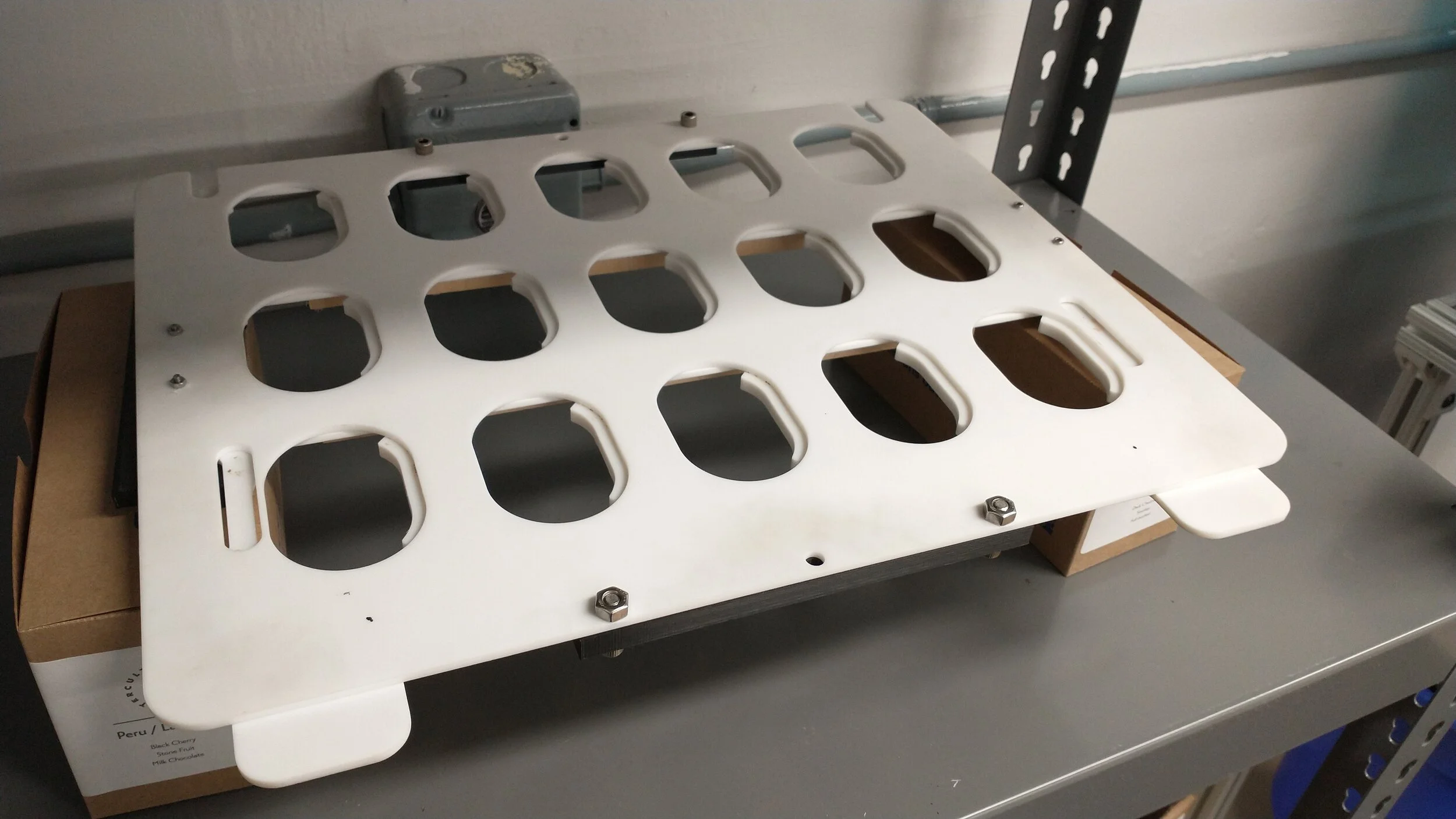
A view of the closed position of the removable tray. Note the support on the left side of each hole. The tray is moved from beneath the machine to a separate system that seals lids on each of the pods.
A view of the open position of the removable tray. The front tabs are connected to a plate that moves the supports on the left side of the holes. When the tabs are moved, the supports move with them, allowing the simultaneous release of all 15 pods into the lid sealing machine.
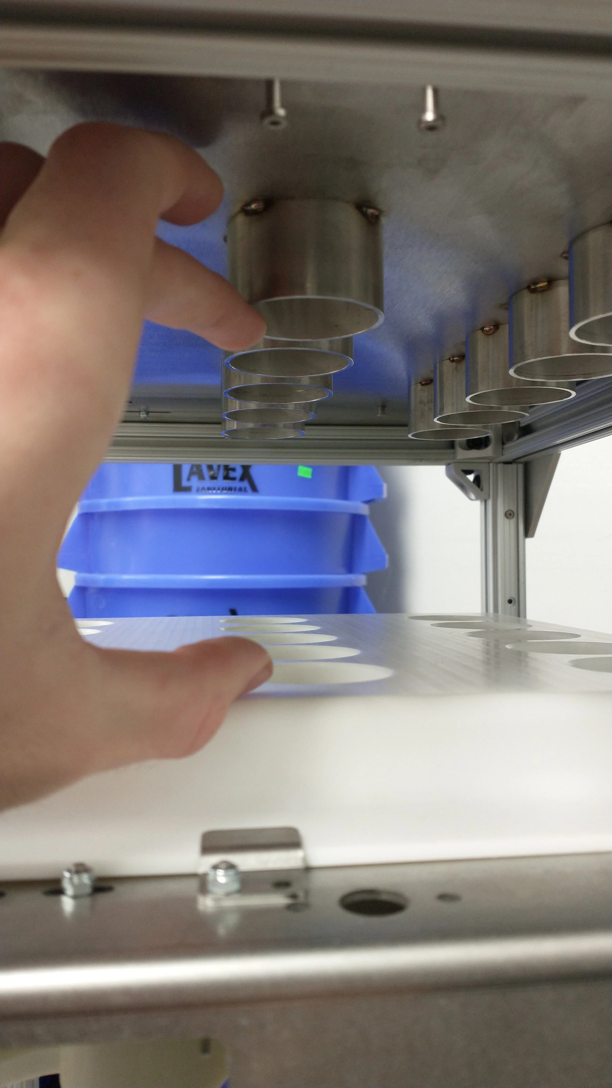
Shown here are the telescoping tubes that determine the amount of beans that go into each pod. A lead screw on each side (not show) determine the depth at which the metal tubes sit in the respective plastic part.
The pneumatic cylinders and linear bearings allow for smooth, automatic movement of the plates required to measure and release the beans.
Both machines next to each other for comparison. Note the height and part number reduction.

CAD of the part situated below the hopper in the first design. While functional, the small diameter holes made for slow cycle times as the vibratory motor slowly unjammed the beans.

CAD of the top separation plate in the first prototype. The slots reduced the contact the beans had with the surrounding stationary plates, reducing the amount of force necessary to move the plate and cycle the machine.
First Prototype Issues and Fixes:
Issue: The prototype did its job well of delivering an accurate mass of beans to each pod, but due to the small diameter of the telescoping tubes, ended up being slower than the desired 5 seconds per cycle due to jamming. The vibratory motor was sized so that it would solve any jams in the machine, but it ended up taking about 30 s per cycle, as the beans take some time to unjam with the vibration.
Fix: Diameter of tubes was increased, which also reduced the overall height of the machine due to shorter tube lengths.
Issue: The machine’s adjustment system was also lacking, mostly due to the complexity of having 4 lead screws that must be individually balanced before they are adjusted as a group. Combining this with a poor tensioner gear design (already removed in the pictures seen above) and the cantilevered location of the pulleys, and the system was just not worth continuing. Shaft collars were installed instead for individual lead screw adjustment.
Fix: Linear guide bearings were installed for both vertical and horizontal movement of the machine. Constraining motion with these allowed for a reduction to only one lead screw on each side. Stepper motors were then to be integrated on each to control motion accurately, although I left the company before I was able to integrate them.
Issue: Assembly and disassembly also left room to be desired. The pulley system had to be disassembled to take apart the machine for washing, and given its complexity, this made the total washing process (disassembly and assembly included) take about 30 to 40 minutes.
Fix: The number of parts was drastically reduced by utilizing the space in between stages of the machine. All removable parts had retention methods that did not require tools, and the number of parts that needed to be removed for washing was decreased. Critically, the adjustment mechanism needed to be removed in the first design to remove the plates, so on the second design I made sure the plates were removable from the mechanism.
Lessons Learned:
As this was my first experience with any sort of granular flow, there were a number of challenges that I ran into that had to be designed around. Starting at the top and working down, the hopper had to interface with the tubes in some manner without leaving paths or spaces for beans to get stuck. I designed an adapter to funnel the beans from the large, square footprint of the hopper to the 15 roughly 1 inch diameter tubes.
The relatively small diameter of the tubes compared to the size of the coffee beans led to jamming of the beans, and would leave some pods with no beans in them at the end of the process. Turns out, as a rough rule of thumb, an orifice diameter of roughly 4x the largest grain size prevents arch formation and jamming, which in this case, would be around 2 in. This would be a recurring issue, as any lip, protruding edge, or burr would cause the beans to form arches across the tubes, preventing the flow of beans into the pods. This was solved by a slightly oversized vibratory motor, mounted to the side of the machine to aid in breaking the arches and freeing the beans from any of the spots in which they were jamming.
Moving down, the top sliding plate (the clear acrylic part with the red handle) acts as a shutoff valve from the hopper to the tubes. This part is roughly 0.75” thick, and has a two-part hole and slot design to prevent beans from being crushed by the shrinking opening as the plate is moved to the closed position. This design allows the beans to only get caught on one edge, so that they are moved back up to the hopper when the plate is moved to the closed position.
Below this plate are the telescoping tubes. These are attached to their respective plates, which can be moved based on the lead screw and pulley system. This allows for quick adjustment of the volume inside the tubes for different kinds of beans. Unfortunately, the first design proved to be unreliable and cumbersome, and shaft collars were installed to prevent the bottom plate from creeping down. The individual lead screws were difficult to adjust, so on the second version, a one lead screw per side design was utilized, with linear sleeve bearings for alignment. With minimal areas for manual adjustment, this makes the machine more robust and easy to use. The new design also does not require disassembly of the adjustment mechanism to wash critical components.
Usability was a big struggle for this project as well, as there were some areas of the prototype that allowed for a user error that would halt function of the machine. For instance, initially the hopper and its adapter to the tubes were not bolted down to the top of the machine, as I had assumed the weight of both components and the beans inside would keep the hopper from moving. Upon usage, however, the user could pull on the top sliding plate in such a way that it would dislocate the hopper and spill beans everywhere. The system also had no safety mechanism for not allowing one plate to move while the other was in a certain position, so if the user wasn’t careful, beans would flow directly from the hopper to the pod tray with no regulation of volume. The second design aimed to automate more functions of the machine, such as using air cylinders to move the plates and a stepper motor and lead screw to adjust the delivered volume without room for user error.